
tinyTag Development Board
A self-contained, complete development platform for sensing, automation and IoT in general.
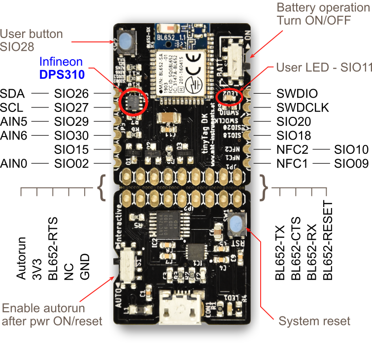
Features
- Built around the nRF52832 core (part of the BL652 module)
- RF link in the 2.4 GHz ISM band (Bluetooth or proprietary)
- 120+ m transmit range (open space, tinyTag to tinyTag)
- Highly sensitive DPS310 pressure sensor
- User programmable tactile button
- User programmable LED
- I2C, NFC and several GPIOs available to the user
- Optimized for battery operation (for example a CR2032 lasts 1 to 2 years)
- Break-out board with USB-to-UART interface
- Programming in SmartBasic (default) or C (optional)
Status: End of Life
Quick start guide
The board comes pre-loaded with a SmartBasic engine. This engine acts as an operating system: it exposes a simple file system for storing applications and a minimal AT command interpreter. The AT commands are used for loading and running an application, for managing the file system and more.
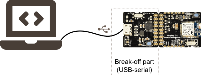
To operate the tinyTag, connect it to a USB port. The board has a USB-to-serial interface on its break-off part.
On the software side, UwTerminalX is the recommended application. It is open source and free, and it serves two goals: communication (including downloading projects to the tinyTag) and compiling SmartBasic projects. To be accurate, UwTerminalX uses an external compiler behind the scenes to build the application, then downloads the resulting code into the tinyTag. Follow the instructions at the link above to install the tool.
Remark: the instructions on this page assume a Windows PC as development platform. Linux or Mac is also possible, but a few details differ.
The first AT commands
- On the tinyTag set the battery operation switch to the OFF position (away from ON) and the autorun switch to the Interactive position.
- Connect a USB cable between the PC and the tinyTag.
- Start UwTerminalX. The first screen asks you to accept the license. After that, the next screen shows the configuration: COM port and parameters. The tinyTag appears as a virtual COM port. Communication parameters are 115200, 8N1, with CTS/RTS handshaking. The device is BL65x, because the tinyTag uses a BL652 module. Click OK when done.
- A terminal window opens and the module answers with
00. If not, press ENTER: the module should answer with00, meaning "ready to accept commands". (All AT commands end with ENTER.)
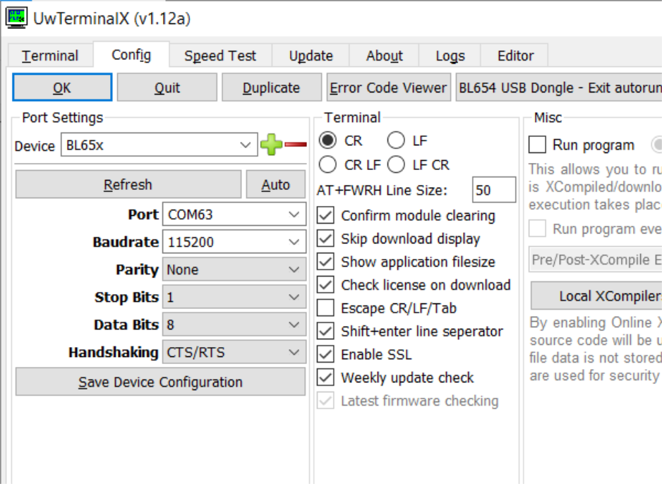
Receiving 00 confirms that the setup is complete and correct, and can be used for development.
Of the many AT commands supported by the SmartBasic engine, these are the most used during development:
AT i 3- Returns the version of the SmartBasic engine. As of May 2021, the newest version is 28.11.8.0r1.
AT i 6- Returns the size of the file system and the amount of free space for storing applications.
AT+dir- Lists the applications stored in the file system (available in the tinyTag and ready to run).
AT+run "app_name"- Starts app_name if it is an application available in the file system, otherwise signals an error.
AT & f*- Erases the complete file system and resets parameters saved in NVM to their default values.
AT & f1- Erases the file system, keeping the values of the NVM parameters.
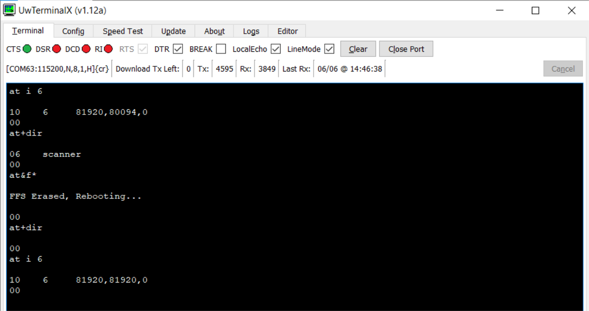
All of these AT commands and typical tinyTag responses are visible in the screenshot below.
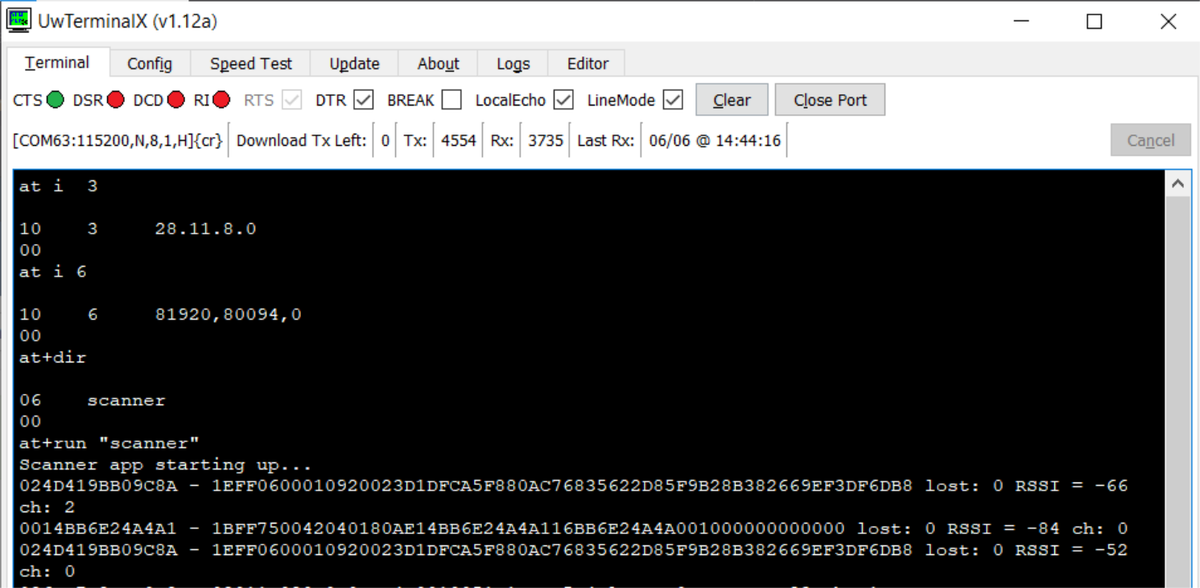
In this case the scanner application was already pre-loaded. Therefore the available space (80094 bytes) is smaller than the total file system space (81920 bytes). The next screenshot shows erasing the file system.
SmartBasic compiler
The compiler is used behind the scenes by UwTerminalX. Each SmartBasic version has a matching compiler, so every time the SmartBasic engine on the tinyTag is updated, the matching compiler must be fetched. UwTerminalX has a sub-folder called "Compilers" for storing them, as the picture below shows.
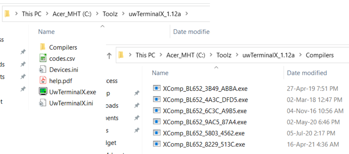
When you trigger the compilation of an application, UwTerminalX reads the version of the SmartBasic engine on the tinyTag and tries to find the matching compiler to build the application. If the compiler is not found, an error is shown and the compilation is aborted.
The SmartBasic engine keeps evolving. Every upgrade package contains both the SmartBasic engine for the tinyTag and the matching compiler. Select one of the SmartBasic upgrade packages (the ZIP files in the Resources section), save it locally, unzip it and open its Firmware sub-folder. The application BL65xUartFwUpgrade.exe there upgrades the tinyTag to that specific SmartBasic version. The matching compiler, XComp_BL652_*.exe, must be copied to the Compilers folder of UwTerminalX. In the newer package (v28_11_8_0_r1) it is in the same Firmware sub-folder; in the older one (v28_9_5_0_r0) it is in the top-level folder of the package.
At this point the famous "Hello World" program can be created and run. Open a text editor and add this code:
print "Hello World!\n"Save the file as helloWorld.sb. (.sb is the preferred extension for SmartBasic files, but it is not mandatory.)
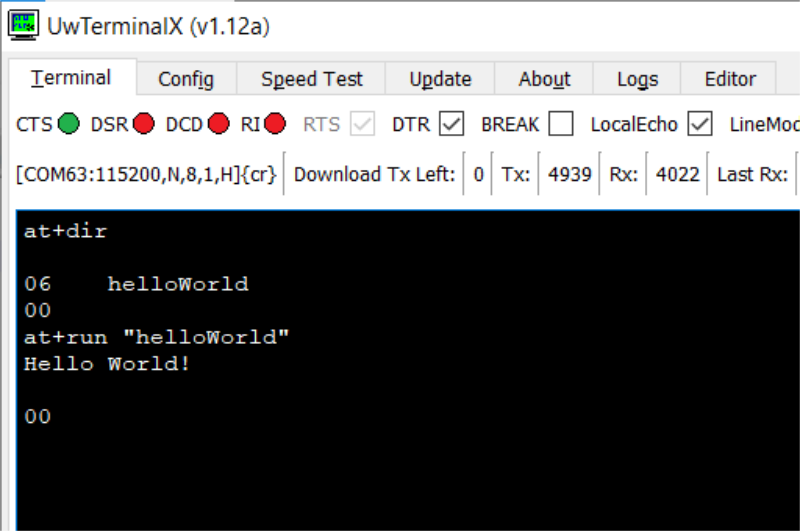
Right-click in UwTerminalX, select "Compile+Load" and pick the helloWorld.sb file. The file is compiled and loaded into the tinyTag. AT+dir then shows the application in the file system, and AT+run "helloWorld" launches it. The screenshot below shows the expected output.
You have now walked through all stages of the development flow. The next sections add more detail and increase the code complexity step by step.
Development flow
Development starts by writing the application. The application is then compiled and finally downloaded into the tinyTag, where it can run.

This sequence is repeated until the application behaves as intended.
The code can be written in any text editor. Notepad++ is a popular choice because it has syntax highlighting. To enable it, select the "Language" menu, then "Define your language..." and "Import" the file smartBASIC(notepad++).xml, which is in the top-level folder of the SmartBasic upgrade packages (see Resources). Finally restart Notepad++. The procedure is described in more detail in this application note.
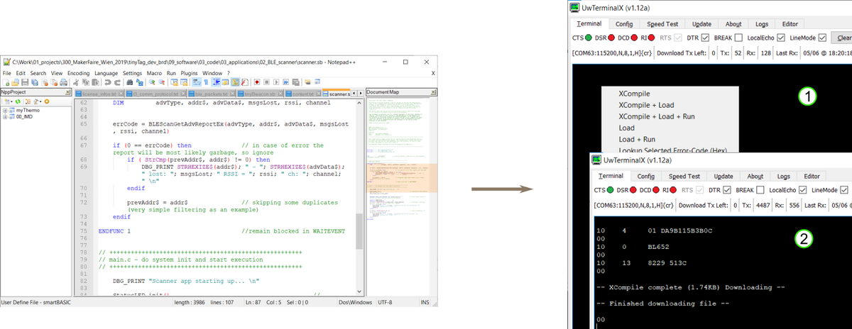
Compilation and download can be combined into a single step. In the picture above, step 1 opens the right-click menu and selects one of the top three options: usually "XCompile + Load" to compile the application and load it into the tinyTag, or "XCompile + Load + Run" to also start it after loading. Step 2 shows the result of a successful compilation and load.
Remark: in case of syntax errors the compilation is interrupted and nothing is loaded into the tinyTag. The first error is highlighted together with a short description.
Debugging
While developing, it is often necessary to inspect what is going on inside the tinyTag and the application. SmartBasic is limited in this respect. Debugging is done with print statements. A typical example:
print "var x = "; x; " and y = "; y; " \n"The print command builds a message by concatenation. The fields separated by ; are joined into a single message and printed over the serial interface (UART).
When development is completed, remove all debug messages from the code. The first debug message left in the code enables the UART, which means a continuous current draw of some mA. That matters for battery operation.
An alternative is to use a GPIO and toggle it a number of times, and observe it with an oscilloscope. This approach has a much lower impact on the application timing. The idea is to indicate various runtime conditions by certain numbers of toggles. See the example below:
#define DIGITAL_OUT 2
#define OUT_LOW 0x00
#define OUT_HI 0x01
#define STRGLO_STRGHI 0x30
#define SIO_20 20

DIM a, errCode

SUB GPIO_toggleN(byVal n as INTEGER)
  dim i

  for i = 1 to n
    GpioWrite(SIO_20, OUT_LOW)
    GpioWrite(SIO_20, OUT_HI)
  next
  GpioWrite(SIO_20, OUT_LOW) // at the end ensure line is left in low state
ENDSUB

// the equivalent of main() function in a .c program starts here
a = 5

// configure the pin as output; start with pin set to low
errCode = GpioSetFunc(SIO_20, DIGITAL_OUT, STRGLO_STRGHI | OUT_LOW)

if (5 == a) then
  GPIO_toggleN(5)
else
  GPIO_toggleN(1)
endif
Copy the code above, compile, load and run it, and observe SIO_20 with the scope. The scope should capture something similar to the screenshot below.
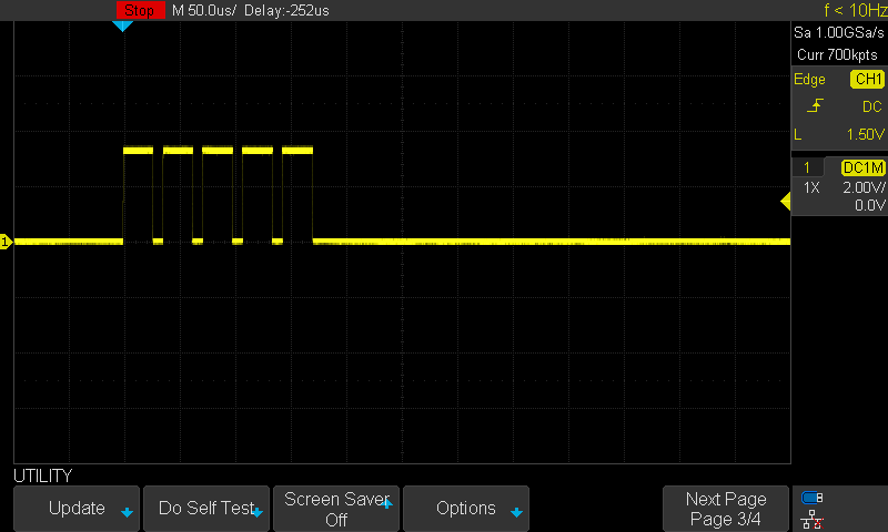
Change the value of a and see what changes.
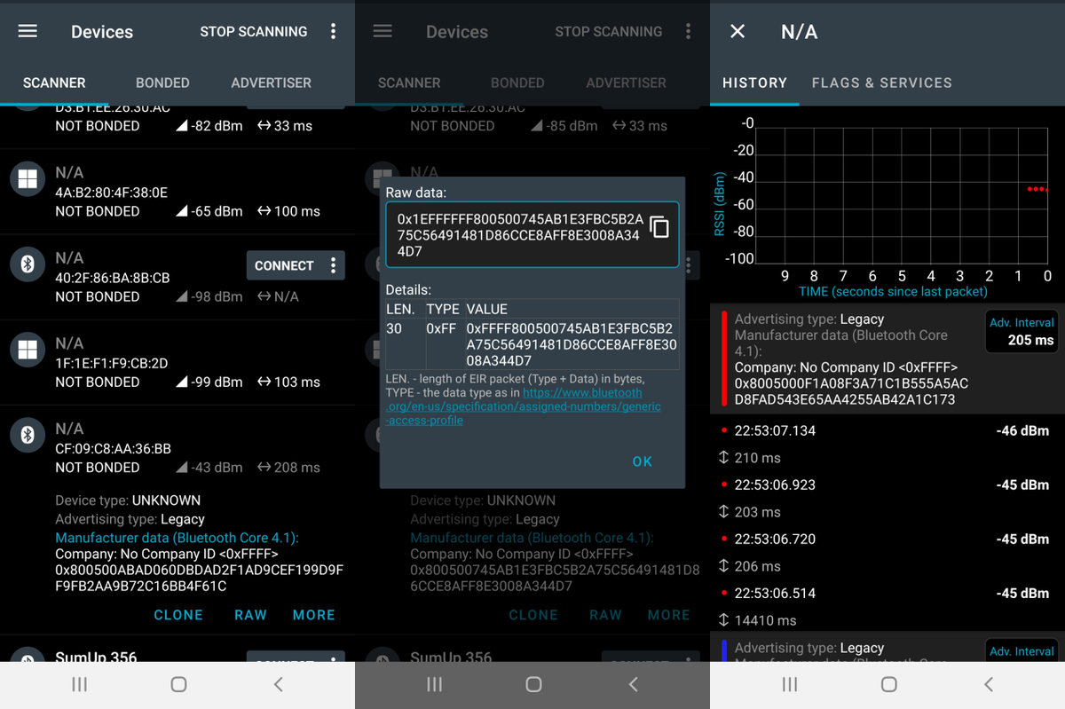
The tinyTag can talk to a mobile phone or a Raspberry Pi via Bluetooth, and Bluetooth communication is debugged with external tools. One of the most affordable is nRF Connect for Mobile, a free application for Android that turns a regular phone into a very capable debugging instrument. nRF Connect shows whether the tinyTag sends something out, whether the data is the expected data, and much more.
The screenshots below show a list of devices detected while scanning, a closer look at the raw data sent by device CF:09:C8:AA:36:BB, and the history of transmitted data.
SmartBasic
SmartBasic is similar to the Basic languages of the 1970s and 1980s, extended to support modern technologies and microcontrollers. Statements are interpreted and executed line by line.
A SmartBasic application can be very short and defined in a single file, or quite complex and spread across several files (modules). One essential detail: once something is defined (a variable, a function and so on), it is visible in all subsequent code, including the imported modules that follow the definition.
SmartBasic is intended for event-based programming. The system spends most of its time asleep, waiting for an event. When an event is triggered, the system wakes up, runs the event handler and goes back to sleep. The application must therefore be designed for event-based operation.
SmartBasic includes support for:
- variables and constants
- control statements (conditionals and loops)
- error and event handling
- a large set of built-in routines
The ultimate reference for what is available, with syntax and usage examples, is the core functionality user guide (PDF, also listed in Resources).
In addition to the core functionality, SmartBasic includes extensions for Bluetooth operation, since the platform is intended for Bluetooth applications. The reference for those is the Bluetooth extensions user guide. Use the one that matches the SmartBasic version on your tinyTag: v28.11.8.0 or v28.9.5.0 (PDF, see Resources).
Simple SmartBasic application
As an example, a simple application defined completely in a single file (simpleApp.sb, also in Resources) is shown below. The application defines a routine that toggles a GPIO n times, which is useful for debugging.
The application runs in a loop. It generates a random number of seconds to use as a sleep interval, toggles the GPIO to indicate that number of seconds and prints the number over the serial interface. Then it sleeps for that many seconds. When the time has elapsed, the application wakes up and the loop repeats.
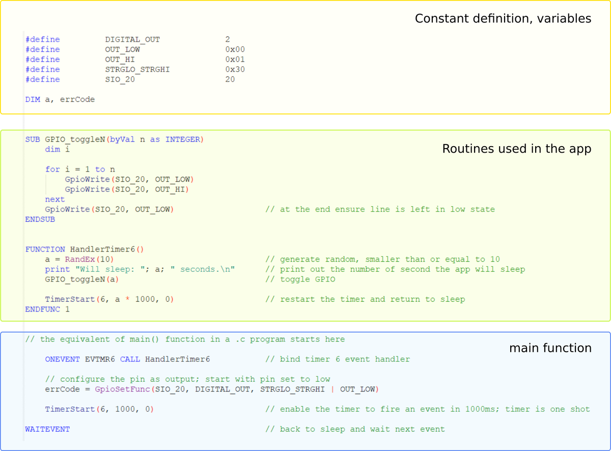
The structure highlighted above is the same whether the application is defined in a single file or spread across several modules. The WAITEVENT statement appears only once, in the "main" function. Everything used in the code must be defined before it is used or be part of the SmartBasic functionality (core or extensions).
Complex SmartBasic application
A complex application needs sensible code partitioning into modules. Remember that everything defined is available in all subsequent code, including imported modules. As the application grows this can turn into a mess. It is therefore preferable to work with local (function or subroutine level) variables as much as possible, which minimizes the risk of accidentally changing something just because it is accessible. Another trick is to encapsulate related functionality in a module and keep it grouped. Access to the module's data should go through a defined set of functions (the module interface), even if the variables would be directly accessible.
As an example, here is a slightly more complex application that periodically reads the pressure and temperature values from the DPS310 sensor and prints them over the serial interface.
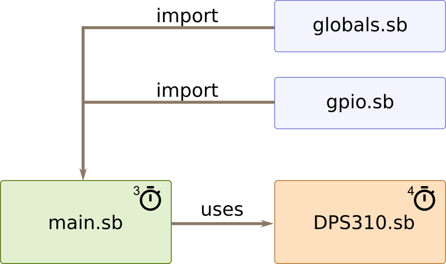
It consists of the four modules shown above. The main module is the application core: the point where execution starts, containing the "main" function. The sensor driver is implemented in its own module, DPS310.sb. The remaining two modules, gpio.sb and globals.sb, contain global constants and GPIO related definitions. The complete application is available as a ZIP download (see Resources).
The application uses timer 3 to trigger a new pressure measurement every 2 seconds. The DPS310 driver is implemented as a self-running unit. Once triggered, it performs a complete measurement and handles the sensor states, timings and messages behind the scenes. At the end, the values are processed and stored in the module's internal variables. The driver notifies the application by posting a message when the measurement and processing are complete. The application can then retrieve the newest measurement through the module's interface (see the recommendation above).
The screenshot below shows typical output. Pressure values depend on location and weather, and this sample application does not consider weather conditions when calculating the altitude.
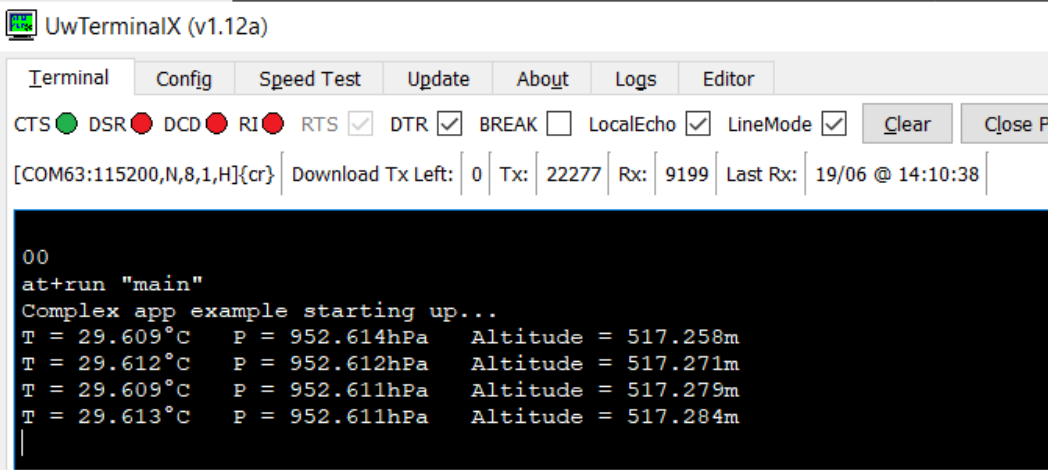
While the application is running, try moving the tinyTag upward and downward (for example 10 cm higher, then 20 cm higher) and watch the sensor readings. This simple exercise gives a direct impression of the incredible sensitivity of the DPS310.
Resources
SmartBasic: upgrade packages and user guides
Each upgrade package contains the SmartBasic engine for the tinyTag, the matching compiler, the upgrade tool and the Notepad++ syntax file. Choose the user guide that matches the package version.
- SmartBasic upgrade package v28_11_8_0_r1
- SmartBasic upgrade package v28_9_5_0_r0
- User guide: smartBASIC core functionality v3.4
- User guide: BL652 smartBASIC extensions v28.11.8.0
- User guide: BL652 smartBASIC extensions v28.9.5.0
Example applications
Hardware documentation
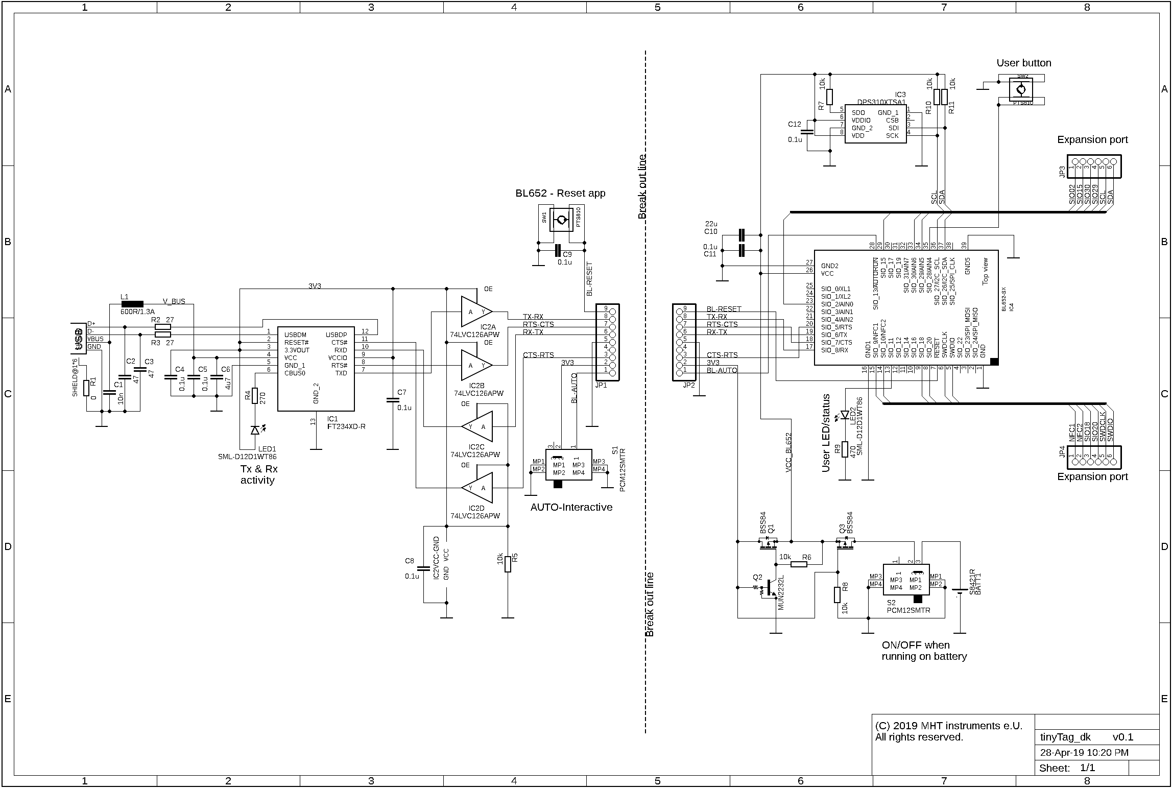
- tinyTag development board schematic (v0.1)
- BL652 module datasheet v2.8
- DPS310 pressure sensor datasheet v1.2
Links
- BL652 series module: documentation and the absolutely latest firmware
- SmartBasic user guide, core functionality (online version)
- UwTerminalX
- Notepad++
- nRF Connect for Mobile